
While I have a lot of broad concepts to explore moving forward, I wanted to do an "Initial Build" per the manual, including getting some initial "steps" being made using the Nomad_Walking_Demo.bsp software provided by CrustCrawler. (See the PBasic Walking Engine page for a description of changes required to the walking engine.)
Things went very well, and followed the provided manual without any significant hitches. I've included some comments on things I might do different in the future. I purchased my kit with the "full upgrade" to the Hi-Tec HSR-5995TG "Robot Servos". As far as physical construction goes, this really had no impact on assembly.
Skipping the notes, here's a picture of the sort-of-completed Nomad:
Before I went too far, I did "semi-build" one leg to make sure the mounting boss on the bottom of the servos would not be a problem. The picture below shows the mounting point on the bottom of the "Robot Servos". This bottom plate can be left in place. It does not need to be swapped with the plain bottom plate.
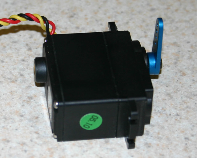
I used a flush cutting nippers to trip the "riser tabs" from 12 of the servos. After using the nipper, I trimmed with an X-Acto knife, and used a mill (flat) file to make sure I had a flat mounting surface. I also drilled 12 of the round servo horns per the manual (Step 1, Chapter 3).
If you are using a drill press, you may also want to drill 6 of the metal servo horns at the same time (Step 29). The manual shows the standard plastic servo horns. The 5995s come with a metal servo horn. I drilled the second hole from the end. [To Do: Get picture of drilled servo horn.]
Again, everything went just like in the instructions. I do have the following notes and comments:
Step 4: I wouldn't attach the servo wires with a wire tie here. I would wait until the legs are assembled, and also tie in the ankle servo wire at the location indicated in this step (see Step 38). This will mean wires "swinging in the wind" for a while, but a few rubber bands or "bread wrapper ties" can solve this (if it is a problem).
Step 6: For this, and all steps involving servo mounting, make sure you have the servos centered (or offset as indicated in the instructions). I found it necessary to cycle the servos a few times by hand to make sure I had "full movement" of the servos. If they are not centered correctly, the walking engine will not work properly.
Step 8: There is an addenda with the manual, explaining that you can also mount the Parallax Servo Controllers on the top deck. I chose to do so. While I think you could do this with the included servo extension wires and some creative routing, I am glad I had 4 extra 12" extension cables. I used extensions on all six ankle and lift servos. I don't have a battery harness in place yet.
Step 9: Because my battery power is still not defined (see Battery Power page) I did not mount the battery brackets.
Step 10: For grease application, I use a veterinary syringe and hypodermic needle. Around here (dairy land) we can get them at the local "Fleet Farm". [To Do: Get picture of syringe]
I have big hands (or as my family says: meat hooks) and steps 19 and 21 were a pain, even with my extensive collection of tweezers, small pliers and hemostats.
On Steps 25 - 27, my links did not come together as shown in the manual. As it turned out, I had about an 1/8 gap between the tie rod ends. I put one leg together, and this actually looked pretty good, at least with the robot servos.
Step 29: The robot servos come with a metal servo horn, and I used the second hole from the end to drill out.
Step 33: I'm not so sure the alignment shown is the best for the robot servos. I've got some tweaking and experimentation to do before I can be sure. [To Do: Add notes on lift linkage orientation and adjustments.]
I connected everything per the manual so that I would have minimal work to do in the Walking Engine. I did not wire tie all the servo wires in place at this time, as this is a "temporary" condition in my case. Eventually, I plan on having 3 PSC units, two for the walking servos, and one for future pan/tilt units. The robot servos are rated at 7.4 Volts, and I plan to power them at that voltage. I will have a voltage regulator set at 5 or six volts for the 3rd PSC to drive any "standard" servos. (See the Battery Power page.)
Once I have the battery power in place, I'll determine where the PSCs will be mounted, and tidy things up.
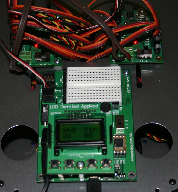
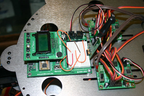
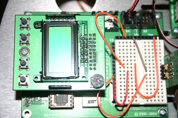
Here's some close ups of the top deck (excuse the glare on the BOE closeup):
|
|
|
|
See the Walking Engine page for initial programming notes.
(This page updated January 18, 2007 with additional close ups of the electronics.)